FlameMaster Flamelet Generation
Overview
FlameMaster produces many individual flamelet solution files that are aggregated together to produce the Stream flamelet table. An individual diffusion flamelet is parameterized by a scalar dissipation rate (\(\chi\)). The flamelet table generation process is composed of five unique stages that must be completed to generate a flamelet table. These five states fall into three main groupings: pre-processing, flamelet generation, and post-processing. The sections below describe the entire process at a high level. Examine the later sections that cover specific types of flamelets for a more detailed breakdown of the exact calls to different programs. A flowchart of the overall process is shown in Figure 6.
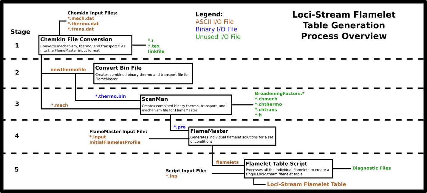
Flamelet table generation process overview. Diagram replicated from work of Brian Richardson.
Pre-Processing
The steps involved with pre-processing involve the create of an appropriate input file for FlameMaster that has reaction, thermodynamic, and transport data encoded within it.
Stage 1 - Chemkin File Conversion
This stage is where the Chemkin input files are converted to FlameMaster formatted ascii files. This first requires three files:
An ascii Chemkin mechanism
An ascii thermodynamics file
An ascii transport file.
All these Chemkin formatted files are converted to FlameMaster formatted ascii files. The three ascii files are converted into two ascii files (1 combined thermo & transport file and 1 mechanism file) in the format used by FlameMaster.
Stage 2 - Convert Bin File
The FlameMaster ascii files created in the previous section for thermodynamics and
transport are converted into a binary format to prepare to be used as
inputs for the next stage. This stage utilizes the FlameMaster
CreateBinFile utility.
Stage 3 - ScanMan
This is the final stage of the pre-processing section. This stage uses
the ScanMan utility in the FlameMaster source code to combine the
ascii mechanism and binary thermodynamics files created in previous two sections
into a single FlameMaster mechanism input file. This file has a
.pre suffix.
Flamelet Generation
The flamelet generation process is where the FlameMaster formatted
mechanism file(*.pre) is used in conjunction with FlameMaster to
typically solve one-dimensional steady-state reactions between streams
of fuel and oxidizers. A suite of solutions that encompass a range of
flow configurations (strain rate of the flow) is the corpus that is used
to generate flamelet tables. These solutions are known as flamelet
solutions and are the elements that are used to build a flamelet table.
Stage 4 - FlameMaster
In this stage, the user runs FlameMaster for a given set of boundary
conditions and sweeps through a parameter space (such as strain-rate for
diffusion flamelets or air-fuel ratios for premixed flamelets) until
enough solutions are obtained that can describe the parameter space.
FlameMaster takes an ascii input file (*.input), a binary mechanism
file (*.pre) and a starting profile (single flamelet solution file) as
the minimum inputs to begin producing additional solutions.
Post-Processing
The portion of the process is where the flamelets that were generated in the previous section are collected and used as an input to a Python utility that generates a flamelet table as an output.
Stage 5 - Flamelet Table Tool
This tool is responsible for reading all flamelet solutions, combining them into an appropriate manifold space, and generating & inserting any additional variables that may be needed within the flamelet table as required by Stream. This would include things such as compressible flamelet table equation of state terms. The the section on the flamelet table tool for more information.
FlameMaster Diffusion Flamelet Tutorial (n-dodecane)
This section focuses on generating a diffusion flamelet table for
use in a combustion simulation. In this example the fuel will be
n-dodecane(N-C12H26) and the oxidizer will be pure oxygen(O2). The flamelet table that
will be generated at the end will be a compressible flamelet table that
uses an ideal gas equation of state and ideal transport properties. In
this example, the counter-flow diffusion flame 1D equations will be
solved using FlameMaster to generate a suite of solutions to be used
for generating the flamelet table. A gitlab repo with the files used in
this example can be found here.
The domain is at a pressure of 6800 psi. The oxidizer stream state is T=700 Kelvin and \(Y_{O2}=1.0\). The fuel stream state is T=650 Kelvin and \(Y_{N-C12H26}= 1.0\).
This will be a full example covering the entire process to create a flamelet table starting from a chemical mechanism file and ending with a Stream formatted flamelet table. It is best to illustrate this processing via a practical example.
A directory structure like the one shown below is
recommended when generating a flamelet table if you are a beginner, but
it is not necessary. Note: The file starting with N-C12H26 would be
your template solution that does not match your desired initial profile.
The initial_profile directory is just to hold the final iteration of the
flamelet solution file that represents your desired conditions. The
mechanism directory is where you will generate the FlameMaster .pre
file.
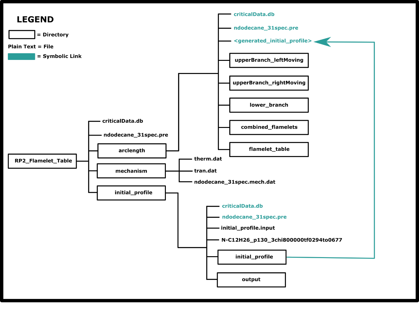
A sample directory that is used by the authors for generating flamelet tables.
Stage 1: Chemkin File Conversion
In following with the steps covered above, start with the three necessary Chemkin ascii files (mechanism, thermo, transport) for n-dodecane.
The Chemkin file conversion scripts are in the FlameMaster directory
under: FlameManTools/CK2FMReinh/. These scripts were created to convert
general reaction mechanisms into a specialized input file format that
FlameMaster uses. There are ascii notes files in that directory that
also document this process in detail. Special transport and thermo
database files are often provided to go along with a particular
mechanism because they contain data on special species that are in a
mechanism which may not be present in a simpler set of transport and
thermo data files. It is a good idea to always check these thermo and
transport data files to make sure all the mechanism species are
included. :ref:` This is a good resource <http://web.eng.ucsd.edu/mae/groups/combustion/mechanism.html>`
for obtaining quality thermo and transport data files.
. This stage has three small sub-steps that must be completed to generate the
final output files for Stage 1.
The starting files for dodecane mechanism are ndodecane_31spec.mech.dat,
ndodecane_31spec.tran.dat, and ndodecane_31spec.thermo.dat.
The process to generate newthermofile required for the ConvertBinFile
script in the Stage 2 is outlined in the following substeps. A Readme
file located in the FlameMaster source under
/FlameManTools/CK2FMReinh/ has a detailed breakdown of each step as well
as each script that is used during this stage.
Step 1: chintrp3seiser
The command to execute is: ./chintrp3seiser
The script will request the following four inputs from the user. The order in which to type them in and press enter is shown below:
ndodecane_31spec.thermo.datndodecane_31spec.mech.data2.ilinkfile
This will generate two outputs: a2.i (the interpreter file) and
linkfile. The next step is to pass the interpreter file to the mechi2tex
utility.
Step 2: mechi2tex
The command to execute is: ./mechi2tex.perl a2.i 1 2
This will generate two outputs: a2.mech and a2.tex. The final step in
this stage is to generate a thermo file for FlameMaster using the
modmech.perl utility.
Step 3: modmech
The command to execute is:
./modmech.perl -t ndodecane_31spec.thermo.dat -r ndodecane_31spec.trans.dat -o
ndodecane_31spec.mech a2.mech
This will generate three outputs: ndodecane_31spec.mech, newthermofile,
a2.mech. At this point, the newthermofile has been created, and the user
can move on to the next stage.
Step 4: (Compressible Flamelet Only) ck2yaml
For a compressible flamelet table one must first also have used the three original ascii files that we started with and to use a Cantera utility to generate a Cantera formatted reaction mechanism file.
Two additional files are needed for compressible flamelet tables:
A Cantera mechanism file(
*.yaml) generated from the same Chemkin input files that created the FlameMaster mechanism file(*.pre).An ascii text file containing the FlameMaster species names from the mechanism and the Cantera species names. Simply the first column being the FlameMaster species and the second column being the Cantera species. The name of this file is not important, it just needs to be provided as the Cantera name species map variable in the flamelet table tool input file.
A sample call to the YAML mechanism generator in Cantera is shown below. If you have Cantera installed in your Python environment, you can run the following command.
ck2yaml.py --input ndodecane_31spec.mech.dat --thermo=thermo.dat --transport=tran.dat --permissive --output=ndodecane
This will generate a ndodecane.yaml file to be used by the flamelet table generation tool.
Stage 2: Convert Bin File
The newthermofile is needed before this stage can be started.
The command to execute is:
./FlameManLibs/CreateBinFile -i newthermofile -o ndodecane_31spec.thermo.bin
This will output a file named ndodecane_31spec.thermo.bin. There is
normally no output printed to the screen from this script during execution.
Stage 3: ScanMan
The ndodecane_31spec.thermo.bin and ndodecane_31spec.mech files are
needed prior to beginning this stage.
The command to execute is shown below.
./FlameManLibs/ScanMan -i ndodecane_31spec.mech -t ndodecane_31spec.thermo.bin
This will output the following files: ndodecane_31spec.pre , and many other
diagnostic files. The ndodecane_31spec.pre file is the final file
that is needed to begin generating flamelets with FlameMaster.
Stage 4: Running FlameMaster
Flamelets can be generated now that a FlameMaster mechanism (.pre file) is available. If a mechanism file is already available, then start from this section. This stage is longer than the previous ones because it must cover the complete execution of FlameMaster. FlameMaster requires three input files to generate flamelets:
FlameMaster input file (
*.input)Starting profile (an initial condition file, with a name in the form of the image below)
Mechanism file (the
*.prefile generated in the previous sections)
FlameMaster generates many flamelet files. Information about the contents of a flamelet file is encoded in the name of the file like what is shown below.

Example file name for a diffusion flamelet solution file from FlameMaster.
FlameMaster requires an initial profile (1D flamelet solution) which
it uses as an initial condition. Profiles can be generated from scratch
(described in the FlameMaster documentation file
FlameleLibraries.pdf), or a previously generated solution can be used
(a template solution). A template solution approach is often the easiest
starting point for users of FlameMaster as it involves an incremental
adjustment of the template solution. To reiterate: in the context of this guide,
a template solution is just a prior solution that you may have available to you.
Parameters that can be adjusted to create an initial starting profile from a pre-existing profile:
Pressure
Fuel Temperature
Oxidizer Temperature
Fuel Composition (mass fractions)
Oxidizer Composition (mass fractions)
It is best to adjust the parameters one-at-a-time, but if the template solution is close to your desired state, changing more than one parameter may result in FlameMaster being able to provide a converged new solution. Use newly generated intermediate solutions during each subsequent parameter adjustment like what is shown in the diagram below.

A series of incremental changes to an input file to generate an initial solution by starting from a different solution file that has different conditions.
When adjusting the temperature, it is a best practice to use increments of 50 K or less. Adjust the pressure in increments of 100 psi or less. These are ad-hoc rules, so adjust the increment size if there is trouble getting a converged solution to generate. Examine the code block below for the lines that can be used to incrementally adjust a template solution towards an appropriate initial condition. The pressure continuation does not support numbers smaller than one, but the user can sometimes just perform a simulation by adjusting the pressure line to be a smaller value and manually step down towards whatever lower pressure is desired.
#### Initial Profile Setup ####
#Note: Oxidizer is 'left' and Fuel is 'right'
#Note: Order below is order of conditions shifting that was done
#ContType is Pressure
#ContInc = 1.04
#ContBound = 46.884e6

#ContType is Temperature
#ContSide is left
#ContInc = -25
#ContBound = 700

#ContType is Temperature
#ContSide is right
#ContInc = 1
#ContBound = 650
Note the following:
Adjust the pressure first if it needs to be changed from the template solution.
FlameMaster does not have an implementation for the continuation to decrease the pressure.
Luckily, the equations are stable when adjusting pressure, so the pressure line in the control file (leaving everything else the same) can be changed to the desired pressure, and FlameMaster should be able to create a solution at the new pressure.
The Temperature adjustment works for increases and decreases.
If FlameMaster is having trouble getting a converged solution with
your specific boundary conditions, consider adjusting the value of the
scalar dissipation rate(Scalar DissipationRate) in the input file. The value of Scalar DissipationRate
that results in extinction might be lower than what was specified in the
template solution that was used. A helpful approach when performing
adjustments to get the desired initial profile is to use the following
command:
FlameMaster -i RP2_initialProfile.input >shift_1.log 2>&1 &
During each of the subsequent adjustments change the number in
shift_1.log to whatever iteration you are on. And do not forget to
adjust the input file to use the correct previous solution for the next
input solution iteration. Below is an image showing a typical S-curve plot
that is generated from the flamelet solutions. This plot is a visual of the
iterative history of the flamelet solutions that were generated.
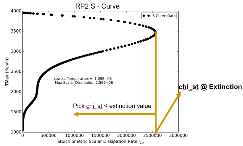
A plot of an S-curve for the n-dodecane flamelet solutions. Each dot represents a flamelet solution.
The FlameMaster arclength continuation mode should be used when computing flamelet solutions. It allows for flamelets to be generated semi-autonomously.
A general approach to generating the flamelet solutions is:
Starting on the upper burning branch, move left using continuation
Starting on the upper branch, move right using continuation
Compute a pure mixing flamelet by setting the scalar dissipation to a value beyond the extinction limit (do not use continuation mode for this)
The initial condition that was generated earlier should be a combusting
solution. The max temperature in the ascii FlameMaster solution can be
visually examined to make sure it is a combusting solution; the header of the ascii file contains
a Tmax entry for the maximum flame temperature. Configure
the control file like what is shown show below to get a leftward
moving set of solutions. Make sure that ArclengthCont is set to TRUE and
that the first value of Scalar DissipationRate is the same as the one in
the initial condition flamelet solution. Setting the second value to a
value less than the first drives the arclength continuation leftward.
Setting the second value to a larger value moves it rightward.
#### Flame ####
ConstLewisNumber is TRUE
LewisNumberFile is LewisNumberOne
ArclengthCont = TRUE

Flame is Counterflow Diffusion in Mixture Fraction Space
EquationOfState is IdealGasLaw

Scalar DissipationRate = 800000 #Starting rate
#Scalar DissipationRate = 800100 #Upper branch - right moving
Scalar DissipationRate = 700000 #Upper branch - left moving
#Scalar DissipationRate = 20e6 #Lower Branchure right point
Generation Process
Create a folder for where you want to generate flamelets at.
Create a set of sub-directories like the ones shown in the image below.
Place the initial profile that you have previously generated it into this new directory.
Generate flamelets for the upper branch moving left & right by adjusting the scalar dissipation rate like what it shown in the control file snippet above.
Take the lowest temperature (
Tstlabel in the output filename) converged right-moving branch solution and move it to thelower_branchdirectory.Adjust the control file to disable arclength continuation, set the initial profile to the one the was generated from the previous step, and set the scalar dissipation rate to be large (usually to the right of the S-curve turning point like the one shown in the S-curve example above).
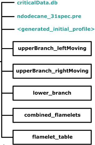
An example directory that can be used for organizing the flamelet generation process.
Stage 5: Post-Processing
Stream has a utility for collecting all the FlameMaster flamelets
and generating a flamelet table. The tool is called the Flamelet Table Tool.
The Python tool requires the following commonly available Python modules: matplotlib, numpy, and scipy.
A summary of the table generation process is as follows.
Compose an input file for the flamelet table tool
Collect all relevant flamelet files together into one location.
Delete non-converged flamelet solutions (
rm -rf *noC)Run the Python script
Examine the generated image files and to make sure the tool generated the table correctly.
The tool generates diagnostic data that the user can use to assess the quality of the generated flamelet table.
A diagnostics folder will be created by the tool with the following information.
A
variable_plotsdirectory that contains a plot of the output variable for each flamelet used to create the table. This can help you to visualize the envelope of the solution space.A
misc_plotsdirectory that contains various quantitative plots that can be used to diagnose issue with a table.Plots of RMS errors between individual flamelets that were used to create the table and the predictions of the table
An S-curve showing the resolution of the table in the S-curve space
A plot of flamelets sorted by progress variable
A series of folders containing the flamelet data for each flamelet and the corresponding predictions of the table at the conditions of that flamelet. There will always be a non-zero error for these plots.
The final step is to create an input file like the one shown below and pass the file to the Flamelet Table Tool. The command to execute it inside of your Python environment where the Flamelet Table Tool is installed is:
flamelet_table_tool input.dat
An example of the control input file can be seen below.
# Author name to appear in flamelet table
AUTHOR Chew Bacca

# Path to the flamelet calculations
PREFIX <path_to_flamelets>/combined_flamelets/

# Describes the folders and name of files of the flamelets. Multiple folders can
be added
FLAMELETPATHS N-C12H26*

# Type of flamelet table (FPVA, FPVC and FPVT)
TABLETYPE FPVC
CLOSURETYPE ThickenedFlame
MECHANISM ndodecane.cti #Cantera formatted chemistry mechanism

#Map between flamelet species name & Cantera mechanism species names
SPECIESNAMEREMAPFILE cantera_flameMaster_species_name_map.txt

EOS ideal #ideal or pengrobinson

# Type of flamelet file to use for creating table(Flamemaster, Cantera)
FLAMELETTYPE Flamemaster

# Characteristics of the flamelet table
NZMEAN 50
NCMEAN 50

# Value of stoichiometric mixture fraction (computed or can be found in any
# FlameMaster flamelet headers)
ZST 0.223431
ZSPACING Zst # Clusters around Zst(highest gradient region)
CSPACING manifold #Manifold or homogenous

# Desired outputs
OUTPUTNAME RP2
OUTPUTVARIABLES W_CO2
OUTPUTTYPE hdf5 vtk
DEFINEPROGVAR Y_H2O Y_H2 Y_CO Y_CO2
TABLE_VERIFICATION TRUE
GENERATE_DIAGNOSTICS TRUE
Premixed Flamelet Generation
Premixed flamelets are 1D solutions where one side of the domain is a premixed mixture of fuel and oxidizer that goes out into a domain and combusts. This is a different configuration than the diffusion flames that are used to create diffusion flamelet tables. As such, these flamelets are used to generate a premixed flamelet tables that has a region of applicability that is slightly different than the area where diffusion flamelet tables are most accurate. Appendix B Appendix B shows a sample control file used for generating premixed flamelets. FlameMaster has documentation about the premixed mode of operation available in the source code for further reading.
The goal with premixed flamelet generation is to create a set of
flamelet solutions that represent a range of fuel-air ratio mixtures
that spans the region of where combustion is feasible. In the control
file there is a parameter named phi that represents this ratio and is
the value that is changed during successive flamelet generations. Like
the diffusion flamelet tutorial, an initial profile for the premixed
flamelet must first be created. The easiest way is to have a premixed
solution that already exists and simply run FlameMaster on that with
the updated conditions specified in the input file and see if a
converged new solution can be obtained to get an appropriate initial
condition solution. The FlameMaster source has some examples of
premixed solutions that can be used as starting points for generating an
initial solution. Running with lower numerical tolerances can sometimes
help in the process of transitioning from a vastly different template
solution to the desired initial condition solution.
The practical methodology for generating a suite of premixed flamelet solutions is as follows:
Get an appropriate initial condition solution to start with.
Using the initial solution, create a series of values of
phiin the input file(premixed.inp) that go from the value ofphiof the initial solution up to a value that is a value of 10 higher, with steps of 0.1.Change the
StartProfilesFileis line in the input file to be the name of the last converged solution written to the/outputdirectory.Delete the old values of
phifrom the input file and generate a new set that starts at the value of the solution from (3) and goes up by a value of 10. E.g. 15.0, 15.1, 15.2, 15.3 … 24.9, 25.0.Repeat this process until no additional converged solutions can be obtained. This is the maximum limit of
phi.Begin with the solution from (2) and go in the opposite direction by creating a list of values of
phiand drop by 0.1 until a lower limit is reached.
The values of the step size of 0.1 and the range of 10 come from
experience with using the FlameMaster code. They are not set in stone
or required. FlameMaster has a semi-automatic mode when a list of phi
values is present in the file, so it will attempt to run all values of
phi that are in the file. The weakness is that the code continues to use
the initial condition for all values of phi, which results in trouble
getting a converged solution when the values of phi become quite
different from the initial condition. Hence why a daisy-chain
method must be used where the last converged solution in a series is
used as the starting initial condition for the next range of larger phi
values. A sample command for calling FlameMaster to generate a premixed
solution is shown below.
FlameMaster -i premixed.inp > run.log 2>&1 &
Examine the flamelets plotted in the figure below and note the horizontal axis showing the mixture fraction range over which flamelet solutions can be generated. These are the upper and lower limits that were discussed above.
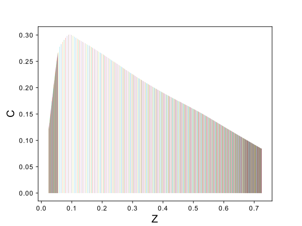
Premixed flamelet manifold.
See the sample file below for the format of the input file to the Flamelet Table Tool to generate a premixed flamelet tables using the flamelets that were generated from the methodology described above.
# Author name to appear in flamelet table
AUTHOR Garrus Vakarian

# Path to the flamelet calculations
PREFIX <path_to_flamelets>

# Describes the folders and name of files of the flamelets. Multiple folders
# can be added
FLAMELETPATHS CH4*

# Type of flamelet table (FPV, FPVT and FPVC)
TABLETYPE FPIC
CLOSURETYPE ThickenedFlame

MECHANISM grimech30.cti

# Map between flamelet species name & Cantera mechanism species names
SPECIESNAMEREMAPFILE cantera_grimech3_species_names.txt

EOS ideal #ideal or pengrobinson

# Type of flamelet file to use for creating table(Flamemaster, Cantera)
FLAMELETTYPE Flamemaster

ZST 0.0548512
ZSPACING zst
CSPACING manifold

# Characteristics of the flamelet table
NZMEAN 201
NCMEAN 201

OUTERHULL_SMOOTHING_ITERATIONS 1

# Desired outputs
OUTPUTNAME  methane_gri3_ideal_fpic_thickened
OUTPUTVARIABLES    W_H2 W_NO
OUTPUTTYPE  vtk hdf5
DEFINEPROGVAR  Y_H2O Y_H2 Y_CO Y_CO2
TABLE_VERIFICATION   TRUE
GENERATE_DIAGNOSTICS    TRUE
Inert Flamelet Generation
Stream supports a flamelet table type that allows for the simulation of combustion in the presence of an inert species that is independent of the fuel and oxidizer streams. In this framework the flamelet tables are parameterized by Z, C, and Y, for thickened-flame type closures. The Y dimension is the inert species mass fraction dimension. In order to construct these tables, a series of counterflow diffusion flamelets need to be obtained from FlameMaster.
The figure below shows the schematic of the basic idea for the interpolation along the Y (diluent fraction) axis.

Simple diagram showing the extra table dimension added for inert tables.
The figure below shows a flow chart of the complete workflow process involved with generating the suite of flamelets that are necessary to create an inert flamelet table. In short, at any given inert level, one will go through the standard process of generating flamelets along the entire S-curve using the arc-length-continuation method, but with species boundary conditions appropriate to that specific inert level. When generating flamelets at a given inert level, the boundary conditions for the incoming fuel and oxidizer species are adjusted to account for the inert component, which is injected into both the fuel and oxidizer sides of the flamelet. For example, in a regular non-inert flamelet for MMH/NTO combustion, one would have the species mass fraction for MMH (\(Y_{MMH}\)) set to unity on the fuel side and the species mass fraction for NTO(\(Y_{NTO}\)) set to unity on the oxidizer side. Assuming the use of Argon (\(Y_{Ar}\)) as the inert substance and an inert mass fraction \(Y_{Ar}= 0.2\) (thus, we are generating flamelets for the \(Y= 0.2\) inert level), the fuel side mass fractions would be set to (\(Y_{MMH}= 0.8\), \(Y_{Ar}= 0.2\)), while the oxidizer side mass fractions would be set to (\(Y_{NTO}= 0.8\), \(Y_{Ar}= 0.2\)). This process would be repeated until FlameMaster fails to provide combusting solutions for the counterflow diffusion flame configuration. At some point the presence of the diluent will extinguish any flames.

Visual depiction of the workflow that is required to generate flamelet solutions having inert boundary conditions for use in the Flamelet Table Tool.
The Flamelet Table Tool is capable to processing the inert flamelets generated as described above and generating 3-D flamelet tables parameterized by (Z, C, Y). Two additional input arguments for the Flamelet Table Tool must be provided by the user as follows:
# Inert Dilution Section
inert_mass_fraction_levels 0 0.2 0.4 0.6 0.8
inert_species_name AR
The first entry is a list of inert species mass fractions that
correspond to the groups of inert mass fraction boundary conditions that
were used to generate the suite of flamelet solutions in FlameMaster.
The tool will parse the boundary condition information that is present
in the flamelet solution files and group all flamelets into their
families of solutions that have inert mass fractions that are closest to
the values provided by inert_mass_fraction_levels. The second entry is a
specification of the name of the inert species as is found in the
flamelet solution. A final step for generating a 3-D flamelet table with
an inert diluent species is to provide a tabletype entry that will
trigger the inert table generation, as shown below.
TABLETYPE fpvc_inert
Currently inert tables are only supported for compressible thickened flame table types. Figure 19 shows a sample control file for generating an inert flamelet table using the Flamelet Table Tool.
# Author name to appear in flamelet table
AUTHOR Urdnot Wrex

# Path to the flamelet calculations
PREFIX ../inert_flamelets/

# Describes the folders and name of files of the flamelets. Multiple folders
# can be added
FLAMELETPATHS Y=0/pruned_flamelets/CH* Y=0.2/pruned_flamelets/CH* Y=0.4/pruned_flamelets/CH* Y=0.6/pruned_flamelets/CH*

# Type of flamelet table (FPV, FPVT and FPVC)
TABLETYPE fpvc_inert
CLOSURETYPE ThickenedFlame #Beta, ThickenedFlame
MECHANISM RChem1_augmented.cti

# Map between flamelet species name & Cantera mechanism species names
SPECIESNAMEREMAPFILE cantera_RChem1_species_names.txt

EOS ideal #ideal or pengrobinson

#Inert dilution
inert_mass_fraction_levels 0 0.2 0.4 0.6
inert_species_name AR

# Type of flamelet file to use for creating table(Flamemaster or Cantera)
FLAMELETTYPE Flamemaster

# Characteristics of the flamelet table
NZMEAN 101
NCMEAN 101
ZST 0.126
ZSPACING zst
CSPACING manifold

# Desired outputs
OUTPUTNAME mmhrfna_ideal_fpvc_inert
OUTPUTVARIABLES Z W_H2O W_CO2
OUTPUTTYPE hdf5 vtk
DEFINEPROGVAR Y_N2 Y_CO Y_CO2 Y_H2O
TABLE_VERIFICATION TRUE
GENERATE_DIAGNOSTICS FALSE
DIAGNOSTIC_OUTPUTS variables
To aid in flamelet organization during the inert table flamelet
generation process, it is advised that the user use the existing PREFIX
and FLAMELETPATHS variables of the Flamelet Table Tool to organize the
flamelets generated for all the inert levels. For example, for the inert
dilution input provided above, one might choose to set these variables
in a similar manner to the following:
# Base path to flamelets.
PREFIX /home/users/neal/mmh_rfna_flamelets/
# Folders under PREFIX directory for flamelets at each inert level
FLAMELETPATHS Y=0/pruned_flamelets/CH\* Y=0.2/pruned_flamelets/CH\* Y=0.4/pruned_flamelets/CH\* Y=0.6/pruned_flamelets/CH\* Y=0.8/pruned_flamelets/CH\*
To summarize the process one last time: You set up a FlameMaster run directory and configure the boundary conditions to have the dilutant species to be whatever value you want for that set of flamelets. You generate the S-curve of flamelets. Then you repeat this process in different directories, for a different value of the diluent. At some point the diluent will cause combustion to fail, so you can stop at that point. The Flamelet Table Tool uses just the two additional inputs that are shown above. The values of the inert mass fractions should match the ones that you use to generate your sets of inert flamelets. It should be able to auto-sort all the flamelets and generate a 3D table with the inert dimension. The tables can be tested by pulling them into Paraview and for Z->X, C->Y, and Y_inert->Z for the coordinates in Paraview, a plot along a X-Z plane can be made and probes around the domain taken to examine the data. Near the Z (Paraview coordinate, not mixture fraction) =1 point, the solution should trend towards the pure diluent state.